This amplifier circuit is used in places where the weak signals are received and to amplify these signals at the antennas with equal input and output impedances.
JFET TRANSISTOR DIAGRAM HOW TO
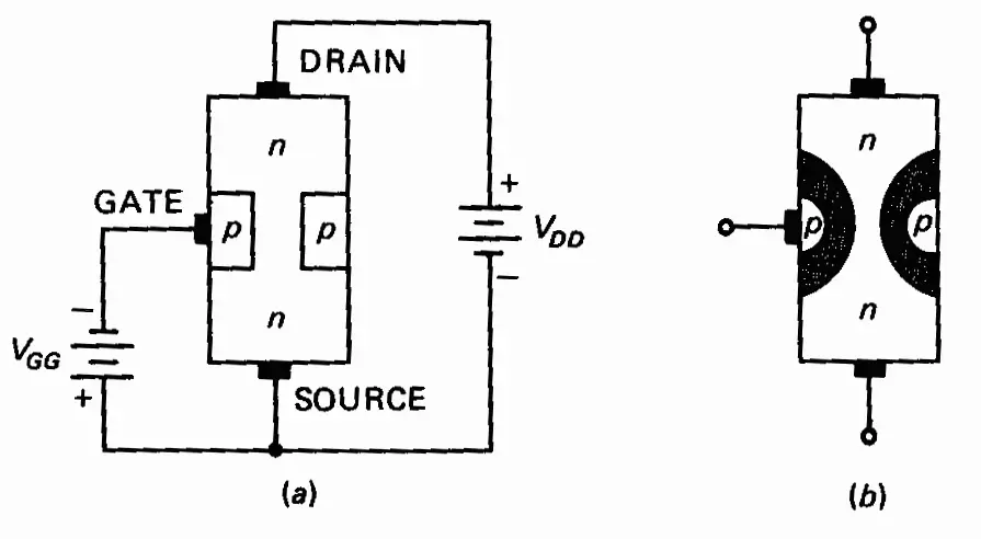
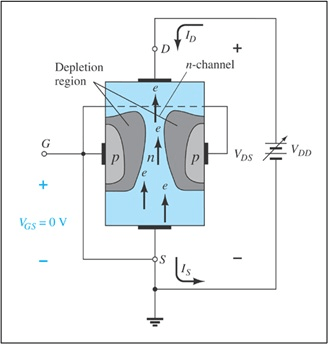
In this section, let’s know how to design FM, AM, SW (short wave) MW (medium wave), and HF (High-Frequency) antenna amplifier circuits using an MPF102 N-channel JFET. Simple Active Antenna Amplifier Circuit for FM/AM/SW/MW Using MPF102 JFET: In this state, it works as a resistor, and the source-to-gate voltage VGS controls the current. The condition in which no current flow occurs through the N-channel MPF102 JFET is called the pinched-off condition. That means the MPF102 JFET blocks the moment of charge carriers from the drain to the source terminal to stop the current flow. At gate voltage=-7.5V, the resistance increases and the current conduction decreases. The components required are Īt gate voltage =0V, the resistance is zero, and the current conduction of JFET is high. The basic circuit diagram shown below explains the working of N-channel JFET. These are also called depletion mode devices and common source N-channel JFET amplifiers. As this is an N-channel JFET, the majority of charge carriers for current conduction are electrons. The MPF102 N-channel JFET is used as a voltage-controlled resistor, amplifier and electronic switch. The reverse transfer capacitance is 3pF.The maximum gate current IDC is 20mAmps.The negative gate-to-source voltage VGS for biasing is -7.5V.The maximum junction temperature is +125☌.The range of storage temperature is -65☌ to +150☌.The maximum power dissipation is 350mWatts.The continuous drain current is 10mAmps.The maximum drain to source current IDC at VGS=0 is 2mAmps to 20mAmps.The maximum drain to source voltage VDS is 25V.It is a general-purpose N-channel JFET that works in depletion mode and is available in TO-92-3 and Pb-free packages.The following are the features and specifications of MPF102 N-channel JFET: The majority of the charge carriers (electrons) move from the source to the drain terminal.įeatures and Technical Specifications of MPF102 JFET: Drain: This terminal is used to control the flowing into the circuit through the drain.


But it is designed in equivalent forms as NTE457 and J113 JFETs. These are no longer manufactured and are also not recommended in new designs. It is a voltage-controlled resistor that works in depletion mode. The MPF102 is an N-channel Junction Field Effect Transistor (JFET) VHF/RF amplifier used in electronic switching and low amplifier circuits. This article gives a brief description of the working of MPF102 N-channel RF or VHF amplifier JFET. Among many, let’s discuss MPF102 N-channel JFET is affordable and rarely used in pre-amplifier circuits, antenna amplifier circuits, RF and VHF amplifier circuits.
JFET TRANSISTOR DIAGRAM TV
It is a voltage-controlled resistor and it is very easy to operate in low amplifier circuits in TV or radio receivers, modulation circuits like FM, AM, SW (Short Wave), etc. Junction Field Effect Transistors (JFETs) are commonly used electronic components due to their high input impedance and low power consumption. In many electronic circuits like small signal amplifier circuits, switching circuits, transfer circuits, etc.


 0 kommentar(er)
